EN-Construction-Products-Tube-structural hollow sections
Our range of both hot finished and cold formed structural hollow sections is one of the broadest available including the leading range of true hot fin..

<a href=/green-steel-future/circular-economy>The future is circular
</a>

<a href=/sustainability/green-steel-solutions/optemis/optemis-carbon-lite>Optemis®Carbon Lite is a declaration-based, low carbon emission steel solution offering the potenti...</a>

<a href=/sustainability/green-steel-solutions/optemis>Optemis represents Tata Steel's green steel journey in the UK.</a>

<a href=/green-steel-future/planning>Planning information and guidance around our transition activity.</a>

<a href=/green-steel-future/media-and-resources>Press releases and downloads
</a>
<a href=/products/hot-rolled/forming>Hot-rolled steel for cold forming is used for bending and deep drawing.Tata Steel's forming grades o...</a>

<a href=/products/hot-rolled/high-strength-steel>Tata Steel’s hot-rolled high-strength, low-alloy (HSLA) grades offer formability and strength for ...</a>

<a href=/products/hot-rolled>Hot-rolled steel offers high quality, consistency in use and value.Our hot-rolled strip steel range ...</a>

<a href=/products/metallic-coated/high-strength-steel>Our range of metallic coated high-strength steels includes micro-alloyed and bake-hardening grades. ...</a>

<a href=/products/metallic-coated/ahss>Dual-phase steels are an AHSS steel that combine high yield strength with good ductility – ensurin...</a>

<a href=/products/metallic-coated/structural-steel>Tata Steel’s metallic coated structural steel behaves reliably in roll-forming and bending process...</a>
<a href=/products/metallic-coated>Tata Steel offers a wide choice of metallic coated steel. Our product range includes forming and str...</a>

<a href=/construction/products/coil-flat-sheet/prefinished-steel-cladding/colorcoat-hps200_ultra>Super durableguaranteed performance.Designed to withstand even the most demanding and aggressive env...</a>

<a href=/construction/products/coil-flat-sheet/prefinished-steel-cladding/colorcoat-prisma>Aesthetics that last,guaranteed.Colorcoat Prisma® demonstrates a step change by utilising cutting e...</a>

<a href=/construction/products/coil-flat-sheet/prefinished-steel-cladding/colorcoat-high-reflect>The optimum reflectivity for an internal liner, maximising daylight and reducing requirements for ar...</a>
<a href=/construction/products/coil-flat-sheet/prefinished-steel-cladding/colorcoat-lg>A leathergrain plastisol product suitable for roof and wall cladding systems where good performance ...</a>
<a href=/construction/products/coil-flat-sheet/prefinished-steel-cladding/colorfarm>Designed specifically to meet the demands of agricultural buildings including a high resistance to a...</a>
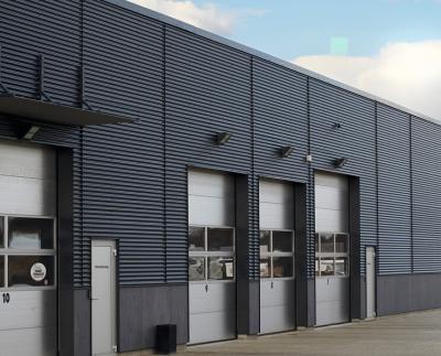
<a href=/construction/products/coil-flat-sheet/prefinished-steel-cladding/colorcoat-pe25>The cost effective pre-finished steel for undemanding applications
Colorcoat® PE 25 is an econom...</a>

<a href=/construction/products/coil-flat-sheet/prefinished-steel-cladding/colorcoat-pe15>The benchmark for internal liner, ensuring light reflectivity and reducing lighting costs.
Colorc...</a>
<a href=/construction/products/coil-flat-sheet/prefinished-steel-cladding/colorcoat-gp>Colorcoat® GP is an economic plastisol product suitable for use in UK and Ireland roof and wall sin...</a>
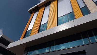
<a href=/construction/products/coil-flat-sheet/prefinished-steel-cladding>Colorcoat®exterior pre-finished steel has been developed specifically to support the aesthetic and ...</a>

<a href=/construction/products/coil-flat-sheet/prefinished-steel-cladding-row/colorcoat-hps200-ultra>Super durable.
Designed to withstand even the most demanding and aggressive environments, Colorco...</a>

<a href=/construction/products/coil-flat-sheet/prefinished-steel-cladding-row/colorcoat-prisma>Aesthetics that last.
Colorcoat Prisma™ demonstrates a step change by utilising cutting edge th...</a>

<a href=/construction/products/coil-flat-sheet/prefinished-steel-cladding/colorcoat-high-reflect>The optimum reflectivity for an internal liner, maximising daylight and reducing requirements for ar...</a>

<a href=/construction/products/coil-flat-sheet/prefinished-steel-cladding/colorcoat-pe25>The cost effective pre-finished steel for undemanding applications
Colorcoat® PE 25 is an econom...</a>

<a href=/construction/products/coil-flat-sheet/prefinished-steel-cladding/colorcoat-pe15>The benchmark for internal liner, ensuring light reflectivity and reducing lighting costs.
Colorc...</a>

<a href=/construction/products/coil-flat-sheet/prefinished-steel-cladding-row>Colorcoat®exterior pre-finished steel has been developed specifically to support the aesthetic and ...</a>

<a href=/construction/products/coil-flat-sheet/prefinished-steel-fit-out>Advantica®pre-finished steel. Setting the benchmark for quality and innovation.</a>

<a href=/construction/services/service-centres/colorsteels-services>Colorsteels is Building Systems UK's service centre product range for pre-finished steel processing....</a>

<a href=/construction/products/coil-flat-sheet/prefinished-steel-cladding>Colorcoat®exterior pre-finished steel has been developed specifically to support the aesthetic and ...</a>

<a href=/services/service-centres/uk-steelpark-service-centre>Supplying an extensive range of sheets and blanks of cold rolled, metallic coated and hot rolled spe...</a>

<a href=/services/service-centres/heavy-gauge-decoiling-uk-llanwern>Customers in the lifting and excavating, energy and power, ship building and heavy engineering marke...</a>

<a href=/services/service-centres/ireland-lisburn>The Ireland Service Centre processes and distributes the full range of Tata Steel's flat products fr...</a>

<a href=/construction/services/service-centres/colorsteels-services>Colorsteels is Building Systems UK's service centre product range for pre-finished steel processing....</a>
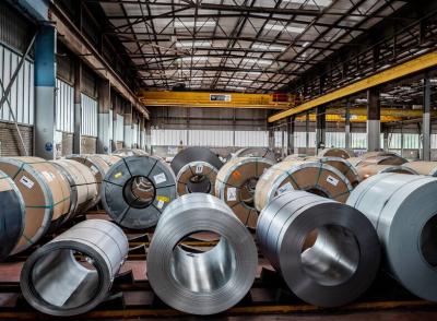
<a href=/services/service-centres>Tata Steel’s extensive distribution network is one of the largest in the UK.These downstream facil...</a>
<a href=/packaging/products/tinplate>We supply a wide range of proven tinplate products for applications including DWI cans, easy-open en...</a>

<a href=/packaging/products/eccs>Well-proven in a range of applications, our tin-free packaging steel (ECCS) delivers reliable qualit...</a>

<a href=/packaging/products/protact>Protactlaminated steel is food-safe and optimised for efficient, sustainable canmaking with opportun...</a>
<a href=/products/packaging-steel>As one of Europe’s leading suppliers of high quality packaging steels, we work closely with our bu...</a>

<a href=/products/electrical-steel>Surahammars Bruk, a Tata Steel enterprise, offers a comprehensive range of electrical steel grades a...</a>
<a href=/products/cold-rolled>Tata Steel UK no longer produces cold-rolled annealed wide coil. However customers can still purchas...</a>
<a href=/construction/products/roof>Building Systems UK (a Tata Steel enterprise) roofing systems, structures and accessories provide hu...</a>

<a href=/construction/products/wall>As well as possessing excellent sustainability credentials, our wall systems are available with a va...</a>
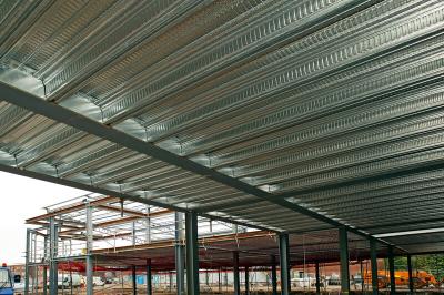
<a href=/construction/products/flooring>Our flooring range includes steel composite floor deck that offers the ultimate steel solution for m...</a>

<a href=/construction/products/other/highway-engineering/vetex>Innovative safety barrier systems for modern highways
With over 50 years experience in the safe...</a>

<a href=/construction/products/other/highway-engineering/barriers>High quality precision-engineered systemsWe pioneered our vehicle restraint system back in 1962. Ove...</a>
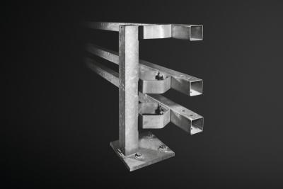
<a href=/construction/products/other/highway-engineering/off-road>Cost effective and flexible traffic control.Off roadbarrier (Armco barrier, safety barrier and crash...</a>

<a href=/construction/products/other/highway-engineering>Our long years of experience in the highway engineering market means we can offer a wide range of pr...</a>
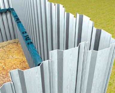
<a href=/construction/products/other/trench-sheeting>Robust solution for both temporary and permanent use.Tata Steel are a leading manufacturer of trench...</a>

<a href=/about-us/sites-and-facilities/shapfell-lime>Our high performance lime products meet the requirements of a wide range of applications.We produce ...</a>

<a href=/construction/products/roof/insulated-roof-panels>Our insulated roof panels and sandwich panels are available in a range of core thicknesses to meet o...</a>

<a href=/construction/products/roof/profiles>We offer a comprehensive range of profiles,built-upsystems and structural roof deck, to meet all you...</a>

<a href=/construction/products/roof>Building Systems UK (a Tata Steel enterprise) roofing systems, structures and accessories provide hu...</a>
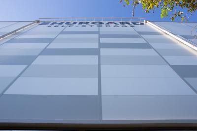
<a href=/construction/products/wall/insulated-panels>Our insulated wall panels and sandwich panels are available in a range of core thicknesses to meet o...</a>
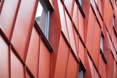
<a href=/construction/products/wall/facades/hub>Our facade systemsform the decorative element of a wall system andare available in bespoke sizes. Hi...</a>
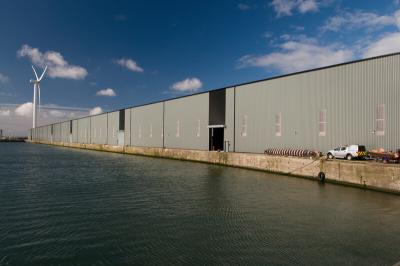
<a href=/construction/products/wall/profiles>We offer a comprehensive range of profiles andbuilt-upsystemsto meet all your cladding requirements.</a>
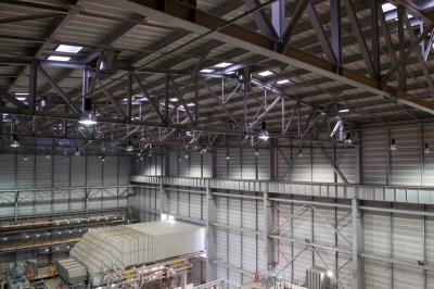
<a href=/construction/products/wall/liner-tray>We meet designers' needs for efficiency, aesthetics and structural performance by offering a compreh...</a>
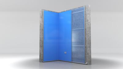
<a href=/construction/products/wall/internal/trimawall-internal-walling-system>Building Systems UK's Trimawall® demountable, modular internal walling system has been designed to ...</a>

<a href=/construction/products/wall>As well as possessing excellent sustainability credentials, our wall systems are available with a va...</a>
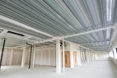
<a href=/construction/products/flooring/composite-floor-deck>Building Systems UK's (a Tata Steel enterprise) metal floor decking range offers the ultimate steel ...</a>
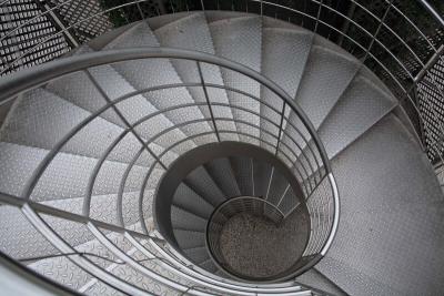
<a href=/products/hot-rolled/durbar-floor-plate>Durbar®is the leading brand of hot-rolled structural steel floor plate, made in the UK for over 50 ...</a>

<a href=/construction/products/flooring>Our flooring range includes steel composite floor deck that offers the ultimate steel solution for m...</a>

<a href=/construction/products/coil-flat-sheet/prefinished-steel-cladding>Colorcoat®exterior pre-finished steel has been developed specifically to support the aesthetic and ...</a>

<a href=/construction/products/coil-flat-sheet/prefinished-steel-cladding-row>Colorcoat®exterior pre-finished steel has been developed specifically to support the aesthetic and ...</a>

<a href=/construction/products/coil-flat-sheet/prefinished-steel-fit-out>Advantica®pre-finished steel. Setting the benchmark for quality and innovation.</a>

<a href=/construction/services/service-centres/colorsteels-services>Colorsteels is Building Systems UK's service centre product range for pre-finished steel processing....</a>

<a href=/construction/products/coil-flat-sheet>Available in a wide variety of finishes and materials our range of market leading products include C...</a>

<a href=/construction/products/renewables/active-solar-air-heating/unglazed-transpired-solar-collector>An active solar air heating solution that provides a renewable pre-heat function.
AnUnglazed Tran...</a>
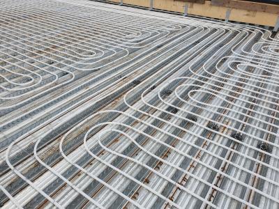
<a href=/construction/products/flooring/composite-floor-deck/comflor-active>ComFlor® Active facilitates truly sustainable control of room temperature in new buildings without ...</a>

<a href=/construction/products/renewables>We are a global supplier of pre-finished steel renewable products for the construction industry
</a>

<a href=/construction/products/cladding-accessories/facias-gutters>We supply a variety of fascias and gutters for a variety of roofs from the smallest domestic to the ...</a>
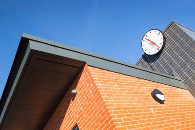
<a href=/construction/products/cladding-accessories/flashings-fabrications>Flashing and fabrications with a superior finish, made to your exact requirements
</a>
<a href=/construction/products/cladding-accessories>From bespoke and standard fabrications for our Colorcoat Urban® range to products for industrial gu...</a>

<a href=/construction/products/other/highway-engineering>Our long years of experience in the highway engineering market means we can offer a wide range of pr...</a>

<a href=/construction/products/other/trench-sheeting>Robust solution for both temporary and permanent use.Tata Steel are a leading manufacturer of trench...</a>

<a href=/construction/modern-methods-of-construction-mmc>Tata Steel are designing and developing products and platforms to enable modern methods of construct</a>

<a href=/construction/products/other/highway-engineering>Our long years of experience in the highway engineering market means we can offer a wide range of pr...</a>

<a href=/construction/products/flooring/comflor/metal-composite-floor-decking-range-overview>One of the most cost effective and efficient ranges of composite floor deck profiles in Europe.Build...</a>
<a href=/construction/products/wall/insulated-panels/formawall>Formawall® is a smooth faced, Secret fixed flat insulated architectural wall panel system with enha...</a>

<a href=/construction/products/wall/insulated-panels/trimapanel>Building Systems UK, a Tata Steel Enterprise, has been a leading manufacturer and supplier of sustai...</a>

<a href=/construction/products/roof/insulated-panels/trisomet>Steel insulated roof panels with optimum performance for water drainage, strength and walkability.Bu...</a>
<a href=/construction/products/roof/profiles/trisobuild>Built-up roof cladding systems can be customised to meet your design requirements including thermal ...</a>

<a href=/construction/products/wall/profiles/trisobuild wall systems>Site assembled, built-up insulated wall systems open up design and performance possibilities for you...</a>

<a href=/construction/products/roof/profiles/roofdek>Building Systems UK(a Tata Steel enterprise) offers a comprehensive range of structural steel roof d...</a>

<a href=/construction/products/wall/internal/trimawall-internal-walling-system>Building Systems UK's Trimawall® demountable, modular internal walling system has been designed to ...</a>
<a href=/construction/products/cladding-accessories/facias-gutters/colocoat-aquatite>A life-times waterproofing - guaranteedBuilding Systems UK's Colorsteels Aquatite®is a pre-finished...</a>

<a href=/construction/key-products/building-systems-uk-building-envelope-solutions-and-structural-steel>The most comprehensive total steel building envelope solution manufactured from one UK source with f...</a>
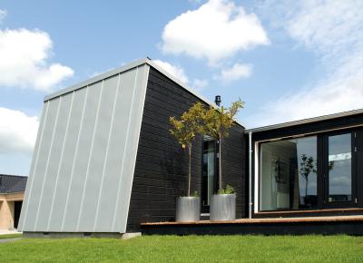
<a href=/construction/products/wall/profiles/clickfals>A Simple and classic solution. ClickFals® is an exciting product from Tata Steel that is revolution...</a>
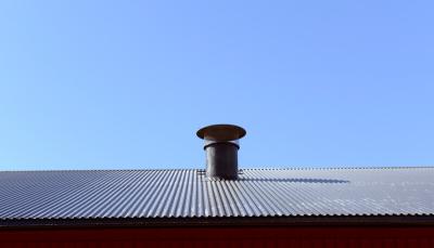
<a href=/construction/products/roof/profiles/trapes>These trapezoidal profiles are classical profiled steel panels for use on roofs or facades
In mod...</a>

<a href=/construction/products/wall/profiles/trapes>These trapezoidal profiles are classical profiled steel panels for use on roofs or facades
In mod...</a>
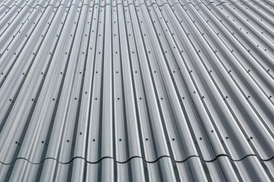
<a href=/construction/products/roof/profiles/sinus>Sinus- a combination of on trend and traditional profiles
Sinus profiles are suitable for use in ...</a>
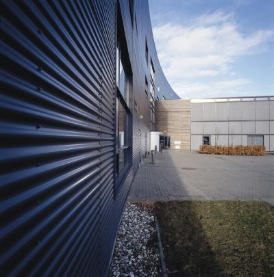
<a href=/construction/products/wall/profiles/sinus>Sinus- a combination of on trend and traditional profiles
Sinus profiles are suitable for use in ...</a>

<a href=/construction/products/roof/profiles/harmonipluss>Effective, practical and highly economical
Aesthetic and highly economical HarmoniPlus® panels a...</a>
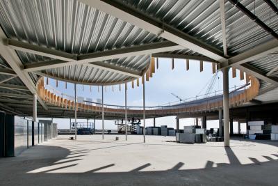
<a href=/construction/products/roof/profiles/hoyprofiler>Versatile and cost-effective
Tata Steel has a wide range of deep deck products with different tec...</a>
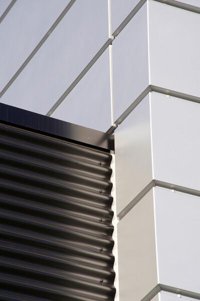
<a href=/construction/products/cladding-accessories/flashings-fabrications/flashings-norway>Freedom in design with enhanced architectural appearance
Standard flashings are available in vari...</a>
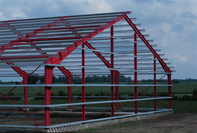
<a href=/construction/products/cladding-accessories/purlins-rails/z-and-c-purlins>Lightweight and strong
Z- and C-purlins combine lightness and strength with cost effectiveness in...</a>

<a href=/construction/products/cladding-accessories/condensation-regulating-fabric/constop-felt>Economical way to prevent condensation problems
This product is a very economical way to prevent ...</a>

<a href=/construction/key-products/building-systems-norway>A comprehensive range of building components and solutions to the building sector in Denmark, Norway</a>

<a href=/construction/products/coil-flat-sheet/prefinished-steel-cladding/colorcoat-hps200_ultra>Super durableguaranteed performance.Designed to withstand even the most demanding and aggressive env...</a>

<a href=/construction/products/coil-flat-sheet/prefinished-steel-cladding/colorcoat-prisma>Aesthetics that last,guaranteed.Colorcoat Prisma® demonstrates a step change by utilising cutting e...</a>
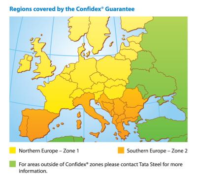
<a href=/construction/services/guarantees/confidex>Offers the most comprehensive guarantee for pre-finished steel products in Europe and provides peace...</a>
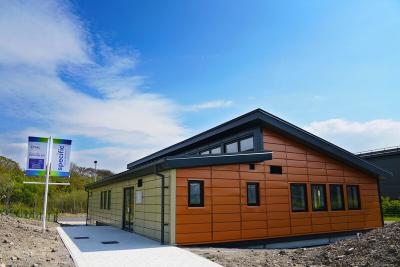
<a href=/construction/key-products/colorcoat>A range of pre-finished steel products which have been used for roof and wall cladding systems on co...</a>
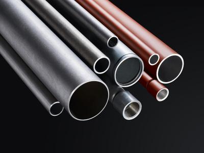
<a href=/construction/products/tube/conveyance/install>Robust and reliable building and engineering services solution.
Install®hot-finished tube has be...</a>

<a href=/construction>Used globally, supplied locally, our innovative construction products have inspired pioneering susta...</a>

<a href=/construction/services/guarantees/confidexhome>Confidex® Home is the performance guarantee for Colorcoat HPS200 Ultra® and Colorcoat Prisma®, wh...</a>
<a href=/construction/services/guarantees/platinum-plus>Platinum®Plus is a system guarantee for 25 years, that covers durability, structural and thermal pe...</a>

<a href=/construction/services/guarantees>Tata Steel offer a wide range of system and product guarantees.
</a>

<a href=/construction/services/guarantees>Tata Steel offer a wide range of system and product guarantees.
</a>

<a href=/construction/services/guarantees>Tata Steel offer a wide range of system and product guarantees.
</a>

<a href=/construction/services/guarantees>Tata Steel offer a wide range of system and product guarantees.
</a>

<a href=/construction/services/cpd>Our range of continuous professional development courses we have on offer in the UK, primarily aimed...</a>

<a href=/construction/services/cpd>Our range of continuous professional development courses we have on offer in the UK, primarily aimed...</a>

<a href=/construction/services/cpd>Our range of continuous professional development courses we have on offer in the UK, primarily aimed...</a>

<a href=/construction/services/digital-tools/comflor-software>ComFlor® 9.0.34 Softwareanalyses each of the ComFlor® composite floor decks in construction stage,...</a>

<a href=/construction/services/digital-tools/roofdek-software>The increasing complexity of roof decking projects makes any software aimed at easing the process ve...</a>
<a href=/construction/services/digital-tools/specification-creator>OurPlatinum® Plus system guaranteeoffers coverage for up to 30 years. Simply fill in your project d...</a>

<a href=/construction/services/digital-tools/CO2-calculator>Tata Steel has today unveiled a new building operational CO2 calculation tool that will help specifi...</a>

<a href=/construction/services/digital-tools/colorcoat-compass>Make an informed colour choice based on availability, feasibility and level of guarantee via our Col...</a>

<a href=/construction/services/digital-tools/tube>Developed to complement the original ‘Blue Book’ website, the new and innovative Celsius® Struc...</a>

<a href=/construction/services/digital-tools/norway-roof-planner/hub>In only a few clicks our Roofplanner will create a complete list of everything you need for your roo...</a>

<a href=/construction/services/digital-tools>At Tata Steel we embrace themove towards a connected, digital world and are continuously developing ...</a>

<a href=/construction/services/service-centres/colorsteels-services>Colorsteels is Building Systems UK's service centre product range for pre-finished steel processing....</a>

<a href=/construction/services/service-centres/colorsteels-services>Colorsteels is Building Systems UK's service centre product range for pre-finished steel processing....</a>

<a href=/construction/services/site-guidance/cladding>Information on the correct way to take delivery of your roof and wall cladding products, and how to ...</a>

<a href=/construction/services/colorcoat-site-guidance>Colorcoat site guidance
</a>

<a href=/construction/services/colour-matching-services>Through our Colour Consaltancy service we are able to offer colour matching and colour availability ...</a>

<a href=/construction>Used globally, supplied locally, our innovative construction products have inspired pioneering susta...</a>

<a href=/construction/Building-systems-uk/sustainable-product-decarbonisation>Building Systems UK Carbon Lite product decarbonisation insetting scheme - Contributing to scope 3 e...</a>

<a href=/construction/sustainability/epd/bespoke-epd-request>Bespoke Environmental Product Declaration (EPD) Request
</a>

<a href=/construction/sustainability/providing-sustainability-information-through-EPDs>As an approved EPD programme operator, Tata Steel can produce product-specific environmental product...</a>

<a href=/construction/sustainability/sustainable-construction-for-long-term-outcomes-tubes>Material efficiency innovations and integrated local supply chains for tube steel provide long-term ...</a>

<a href=/construction/sustainability/design-for-circular-economy>The Bruntland Report, published in 1987, developed guiding principles for sustainable development as...</a>

<a href=/construction/sustainability/providing-sustainability-transparency-in-reporting>It isn’t enough simply to say that materials and products are sustainable - it has to be verifiabl...</a>

<a href=/construction/sustainability/responsible-steel-supplier>Tackling a climate and biodiversity emergency, and delivering social value, requires responsibility ...</a>
<a href=/construction/sustainability-three-pillars>Tata Steel is meeting the combined challenges of climate change, the circular economy, and responsib...</a>

<a href=/construction/applications/industrial>Tata Steel Construction can provide architects, engineers and surveyors with the highest quality of ...</a>

<a href=/construction/applications/distribution>Tata Steel Construction can provide architects, engineers and surveyors with the highest quality of ...</a>

<a href=/construction/applications/commercial>Tata Steel Construction can provide architects, engineers and surveyors with the highest quality of ...</a>

<a href=/construction/applications/healthcare>Tata Steel Construction can provide architects, engineers and surveyors with the highest quality of ...</a>

<a href=/construction/applications/education>Tata Steel Construction can provide architects, engineers and surveyors with the highest quality of ...</a>

<a href=/construction/applications/Retail>Tata Steel Construction can provide architects, engineers and surveyors with the highest quality of ...</a>

<a href=/construction/applications/Residential>Tata Steel Construction can provide architects, engineers and surveyors with the highest quality of ...</a>

<a href=/construction/applications/stadia>Tata Steel Construction can provide architects, engineers and surveyors with the highest quality of ...</a>

<a href=/construction/applications/leisure>Tata Steel Construction can provide architects, engineers and surveyors with the highest quality of ...</a>

<a href=/construction/applications/agriculture2>Tata Steel Construction can provide architects, engineers and surveyors with the highest quality of ...</a>

<a href=/construction/applications/transport>Tata Steel Construction can provide architects, engineers and surveyors with the highest quality of ...</a>

<a href=/construction/applications/energy>Tata Steel Construction can provide architects, engineers and surveyors with the highest quality of ...</a>

<a href=/construction/applications>Tata Steel Construction can provide architects, engineers and surveyors with the highest quality of ...</a>

<a href=/construction/services/cpd/arrange-webinar>Tata Steel provide free CPD seminars either face to face or online. These can be booked at any time ...</a>

<a href=/construction/blogs-news/blogs>Here you can find our latest blogs for Tata Steel in Construction
</a>

<a href=/construction/blogs-news/news>Here you can find our latest news for construction and infrastructure.
</a>

<a href=/construction/tata-steel/podcasts>Our range of podcasts cover some of the key areas in the world of steel in construction from intervi...</a>

<a href=/construction/blogs-news/blogs>Here you can find our latest blogs for Tata Steel in Construction
</a>
<a href=/engineering/key-products>Our key products add value to customers and end applications.
</a>

<a href=/products/hot-rolled/forming>Hot-rolled steel for cold forming is used for bending and deep drawing.Tata Steel's forming grades o...</a>

<a href=/products/hot-rolled/high-strength-steel>Tata Steel’s hot-rolled high-strength, low-alloy (HSLA) grades offer formability and strength for ...</a>

<a href=/products/hot-rolled/ahss>Tata Steel’s FB590 hot-rolled advanced high strength steels has been developed primarily to meet y...</a>

<a href=/products/hot-rolled/structural-steel>The guaranteed strength and good weldability of our hot-rolled structural steel help ensure ease of ...</a>

<a href=/products/hot-rolled/durbar-floor-plate>Durbar®is the leading brand of hot-rolled structural steel floor plate, made in the UK for over 50 ...</a>

<a href=/products/hot-rolled/heat-treatable-steel>Tata Steel offers a choice of hot-rolled heat-treatable steelsHeat-treatable steels offer advantages...</a>

<a href=/products/hot-rolled/gas-cylinders>Tata Steel’s structural steel for gas cylinders offers excellent deep-drawing properties and welda...</a>

<a href=/products/hot-rolled>Hot-rolled steel offers high quality, consistency in use and value.Our hot-rolled strip steel range ...</a>

<a href=/products/metallic-coated/high-strength-steel>Our range of metallic coated high-strength steels includes micro-alloyed and bake-hardening grades. ...</a>

<a href=/products/metallic-coated/ahss>Dual-phase steels are an AHSS steel that combine high yield strength with good ductility – ensurin...</a>

<a href=/products/metallic-coated>Tata Steel offers a wide choice of metallic coated steel. Our product range includes forming and str...</a>
<a href=/engineering/products/tubes>We have one of the broadest ranges of welded tube from any steel manufacturer. Our expertise in the ...</a>

<a href=/products/electrical-steel>Surahammars Bruk, a Tata Steel enterprise, offers a comprehensive range of electrical steel grades a...</a>

<a href=/products/cold-rolled>Tata Steel UK no longer produces cold-rolled annealed wide coil. However customers can still purchas...</a>

<a href=/engineering/products>Working together with the world’s leading equipment makers, steel processors and domestic applianc...</a>

<a href=/engineering/applications/agriculture-and-forestry>Agriculture and forestry machinery users expect their equipment to be efficient, productive and robu</a>

<a href=/engineering/applications/construction-equipment>Working together, we can meet your growing needs across all types of construction and handling equip</a>

<a href=/engineering/applications/consumer-products>Domestic appliances, furniture,sanitaryand radiators.Quality steel making your consumer products mor...</a>

<a href=/engineering/applications/industrial>A huge variety of industrial applications, from drums and gas bottles to racking and shelving, and s</a>
<a href=/engineering/applications/steel-processors>Re-rollers, profilers, tube makers, coating lines.Supplying material you and your customers can rely</a>

<a href=/engineering/applications/transportation>Our steels are used in trucks, trailers, trains and ships. Our expertise is in finding the right sol</a>

<a href=/engineering/applications>Construction equipment applications, consumer products and more.</a>

<a href=/engineering/case-studies/hyster-yale>Opportunities for Hyster Yale to deliver lower total cost of ownership to its customers
</a>

<a href=/engineering/case-studies/jcb-landpower>EnablingJCB to develop an optimally-designed next-generation tractor
</a>

<a href=/engineering/case-studies>We can make a real difference to your performance by understanding your business and delivering stee...</a>

<a href=/services/nexus>Nexus is the new online customer portal designed specifically for Tata Steel's customers.</a>

<a href=/engineering/services>Customer Technical Services offer technical consultancy and hands-on support tuned to your needs and...</a>

<a href=/Services>Overview of Tata Steel in Europe's services
</a>

<a href=/engineering/blog>Read our latest blogs here for Tata Steel in Engineering
</a>
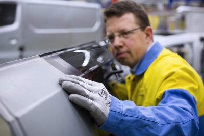
<a href=/automotive/key-products/magizinc>MagiZinc®: advanced hot-dip galvanised coating for inner parts and outer panels.</a>
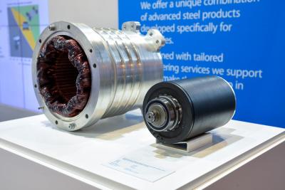
<a href=/automotive/key-products/hi-lite>Hi-Lite:a thin non-oriented electrical steel for efficient and high-performance electric motors.
</a>

<a href=/automotive/key-products>Key products in the Automotive product portfolio
</a>

<a href=/products/hot-rolled/high-strength-steel>Tata Steel’s hot-rolled high-strength, low-alloy (HSLA) grades offer formability and strength for ...</a>

<a href=/products/hot-rolled/ahss>Tata Steel’s FB590 hot-rolled advanced high strength steels has been developed primarily to meet y...</a>

<a href=/products/hot-rolled/heat-treatable-steel>Tata Steel offers a choice of hot-rolled heat-treatable steelsHeat-treatable steels offer advantages...</a>

<a href=/products/hot-rolled>Hot-rolled steel offers high quality, consistency in use and value.Our hot-rolled strip steel range ...</a>

<a href=/products/metallic-coated>Tata Steel offers a wide choice of metallic coated steel. Our product range includes forming and str...</a>

<a href=/products/electrical-steel>Surahammars Bruk, a Tata Steel enterprise, offers a comprehensive range of electrical steel grades a...</a>

<a href=/products/cold-rolled>Tata Steel UK no longer produces cold-rolled annealed wide coil. However customers can still purchas...</a>
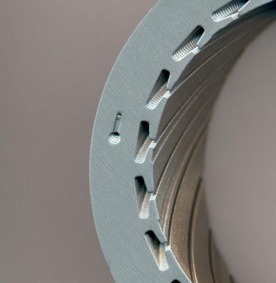
<a href=/automotive/applications/e-motors>
Preferred partner for high efficiency thin gauge electrical steel enabling next generation designs</a>

<a href=/automotive/applications/seating>
Your expert partner in steel design for seating.
</a>

<a href=/automotive/applications/body-in-white>
Supporting you from concept to series production. Increased energy absorption in BIW parts, reduci...</a>

<a href=/automotive/applications/chassis-and-suspension>
Helping you strike the balance in chassis design.
</a>
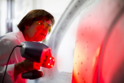
<a href=/automotive/applications/outer-panels>High-end vehicle aesthetics for attractive design features and excellent surface finish.</a>
<a href=/automotive/applications>
Tata Steel offers a wide, multi-product portfolio of strip, tubes and forging steels, including a ...</a>

<a href=/automotive/industry-themes/sustainability/decarbonisation>
Electrification will see significant reductions inuse-phase emissions.
</a>

<a href=/automotive/industry-themes/sustainability/resource-efficiency>The circular economy is based on maximising the use of resources and minimising waste.</a>

<a href=/automotive/industry-themes/sustainability>Working towards vehicles that are fully sustainable
</a>

<a href=/automotive/industry-themes/electrification>Steels for the most important components of the electric vehicle.</a>

<a href=/automotive/industry-themes/digitalisation>Smarter technologies and services for a sustainable automotive value chain
</a>

<a href=/automotive/industry-themes>
Many of our products and technical developments are focused around these key industry themes.
</a>

<a href=/automotive/aurora-online>High quality data and expert advice to make your simulations easier to set up and more accurate.
</a>

<a href=/automotive/blog>Read our latest blogs here for Tata Steel in Automotive
</a>

<a href=/packaging/products/tinplate>We supply a wide range of proven tinplate products for applications including DWI cans, easy-open en...</a>

<a href=/packaging/products/eccs>Well-proven in a range of applications, our tin-free packaging steel (ECCS) delivers reliable qualit...</a>

<a href=/packaging/products/protact>Protactlaminated steel is food-safe and optimised for efficient, sustainable canmaking with opportun...</a>

<a href=/products/packaging-steel>As one of Europe’s leading suppliers of high quality packaging steels, we work closely with our bu...</a>
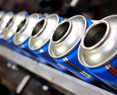
<a href=/products/packaging-steel>As one of Europe’s leading suppliers of high quality packaging steels, we work closely with our bu...</a>

<a href=/products/packaging-steel>As one of Europe’s leading suppliers of high quality packaging steels, we work closely with our bu...</a>
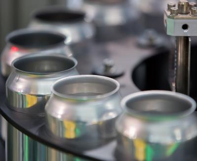
<a href=/products/packaging-steel>As one of Europe’s leading suppliers of high quality packaging steels, we work closely with our bu...</a>
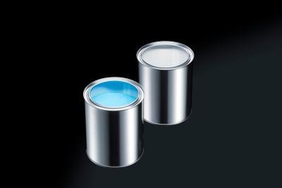
<a href=/products/packaging-steel>As one of Europe’s leading suppliers of high quality packaging steels, we work closely with our bu...</a>

<a href=/products/packaging-steel>As one of Europe’s leading suppliers of high quality packaging steels, we work closely with our bu...</a>

<a href=/packaging/applications>Our packaging steel products are designedfor a diverse range ofapplications from aerosols to food ca...</a>

<a href=/packaging/sustainability>Steel is the world’s most sustainable packaging material. It protects and preserves its contents a...</a>
<a href=/packaging/case-studies/bonduelle>Two thirds of Dutch consumers didn'tknow that a can is endlessly recyclable according to consumer re...</a>

<a href=/packaging/case-studies/snert>Joris Bijdendijk is a renowned Dutch chef at the Michelin-starred RIJKS restaurant, located next to ...</a>

<a href=/packaging/case-study/calvo-vuelca-facil>Consumers, from older users to children can sometimes find traditional tuna cans difficult to use du...</a>

<a href=/packaging/case-studies>We can make a real difference to your performance by understanding your business and delivering stee...</a>

<a href=/packaging/technology/innovation-centre>The Innovation Centre provides the technical knowledge and skills that helps us keep our products at...</a>

<a href=/packaging/technology/product-development>Our Product development team draws on a solid foundation in metallurgy, the latest developments in c...</a>

<a href=/packaging/technology>Our Product Development team draws on a solid foundation in metallurgy, the latest developments in c...</a>
<a href=/packaging/blogs-news/blogs>Read our latest blogs here for Tata Steel in Packaging
</a>

<a href=/services/service-centres/uk-steelpark-service-centre>Supplying an extensive range of sheets and blanks of cold rolled, metallic coated and hot rolled spe...</a>

<a href=/services/service-centres/heavy-gauge-decoiling-uk-llanwern>Customers in the lifting and excavating, energy and power, ship building and heavy engineering marke...</a>

<a href=/services/service-centres/ireland-lisburn>The Ireland Service Centre processes and distributes the full range of Tata Steel's flat products fr...</a>

<a href=/construction/services/service-centres/colorsteels-services>Colorsteels is Building Systems UK's service centre product range for pre-finished steel processing....</a>

<a href=/about-us/at-a-glance>Tata Steel is one of the world’s most geographically diversified steel producerswith operations in...</a>

<a href=/about-us/our-strategy>Our mission is to build the leading European steel business thatis sustainable in every sense
</a>

<a href=/about-us/organisation-and-leaders>Overview of Tata Steel UK and information about the members of the Tata Steel UK Board</a>

<a href=/about-us/our-people>We recognise that our people are the primary source of our competitiveness.</a>
<a href=/about-us/our-heritage>Tata Steel was established in India in 1907 and the first ingot of steel was made at Jamshedpur in I...</a>

<a href=/about-us/our-communities/community-partnership-programme>Tata Steelcontribution to communities'economic and social well-being through a proactive Community P...</a>

<a href=/about-us/our-communities>We aim to positively impact the communities in which we operate.</a>

<a href=/about-us/ethical-behaviour/code-of-conduct>Company code of conduct
</a>

<a href=/sustainability/ethical-behaviour/international-rbc-agreement-for-the-metals-sector>International RBC agreement for the metals sector
</a>

<a href=/about-us/ethical-behaviour>Ethical behaviour is intrinsic to the way we conduct our business</a>

<a href=/services/service-centres/heavy-gauge-decoiling-uk-llanwern>Customers in the lifting and excavating, energy and power, ship building and heavy engineering marke...</a>

<a href=/services/service-centres/ireland-lisburn>The Ireland Service Centre processes and distributes the full range of Tata Steel's flat products fr...</a>

<a href=/construction/services/service-centres/colorsteels-services>Colorsteels is Building Systems UK's service centre product range for pre-finished steel processing....</a>

<a href=/services/service-centres/uk-steelpark-service-centre>Supplying an extensive range of sheets and blanks of cold rolled, metallic coated and hot rolled spe...</a>

<a href=/services/service-centres>Tata Steel’s extensive distribution network is one of the largest in the UK.These downstream facil...</a>

<a href=/about-us/sites-and-facilities/shapfell-lime>Our high performance lime products meet the requirements of a wide range of applications.We produce ...</a>

<a href=/about-us/sites-and-facilities/certificates>List of approval certificates by Country covering Tata Steel's European business entities and sites.</a>

<a href=/about-us/our-operations>Sites and Facilities of Tata Steel in Europe</a>

<a href=/media/latest-news>Latest news from Tata Steel in Europe
</a>

<a href=/media/social-media>Social media channels from Tata Steel in Europe
</a>

<a href=/jobs/apprentices>An apprenticeship at Tata Steel is the first step of a rewarding career. We offer a diverse range of...</a>

<a href=/jobs/graduates>Our two-year graduate programme offers excellent opportunities for individuals who want to apply and...</a>

<a href=/jobs/professionals>Engineering and technical innovation is at the very heart of our business.</a>
<a href=/jobs/placements>Internships are a hugely valuable experience for undergraduates, a chance to put theory into practic...</a>

<a href=/jobs/working-at-tata-steel/benefits>Tata Steel UK offers competitive compensation, learning and development opportunities, an inclusive ...</a>

<a href=/jobs/working-at-tata-steel/locations>Here, you can find out more about our locations across the UK. We have sites throughout the UK, and ...</a>

<a href=/jobs/working-at-tata-steel/employee-networks>Employee networks play a vital role in fosteringa positive work environment and maintaining strong e...</a>

<a href=/jobs/working-at-tata-steel>Here, you can find out more about our locations across the UK. We have sites throughout the UK, and ...</a>

<a href=/jobs/employability-hub>We have created this space, to support you. Irrespective of your career stage, whether you are just ...</a>

<a href=/green-steel-future>Tata Steel UK's plan to decarbonise.</a>

<a href=/jobs/get-in-touch-contact-us>You’ll discover an organisation with the ambition and resources, backed up by the commitment to tr...</a>

Structural hollow sections can provide not only an efficient but also an elegant solution for structural steelwork. Getting the most out of them depends not only on section sizing, but equally on the design of joints – and it is important that this is considered at design stage to avoid unnecessary re-design and the associated cost implication when it comes to fabrication.
A properly designed steel construction using structural hollow sections will nearly always be lighter in material weight than one made with open section profiles. Less steel also equates to lower embodied CO2 emissions. Structural hollow sections have a higher strength to weight ratio than open section profiles, such as I-, H- and L- sections. They also require a much smaller amount of coating material because of their lower external area. Even though they may be more expensive than open section profiles on a per tonne basis, the overall weight saving of steel and protective coatings will very often result in a much more cost effective solution.
Member sizing has a direct effect on both the joint resistance and the cost of fabrication because structural hollow sections are generally welded directly to each other. In order to obtain a technically secure, economic and architecturally pleasing structure, the architect and design engineer must be aware of the effects that their design decisions will have on the joint resistance, fabrication, assembly and the erection.
Considerable international research into the behaviour of lattice type welded joints has enabled design recommendations that include the large majority of manufactured structural hollow sections. These design recommendations were originally developed by ourselves in collaboration with CIDECT (Comité International pour la Développement et l’Étude de la Construction Tubulaire) and the IIW (International Institute of Welding) and have since been incorporated into the European design standards. These form the basis of Eurocode 1-8 and are detailed in the Tata Steel publication “Design of welded joints”.
When looking at jointing for structural hollow sections, there are five main types of joints used in design that cover the majority of connections. They are T-, Y-, X-, N- and K-joints, with the N- and K-joints being either gap or overlap. These standard joints are all 2-dimensional, but for multi-planar structures (for example as used in triangular or box trusses as well as some complex structures) the joint types are similar and design is done in a similar way with a multi-planar factor added.
For a typical application in a medium-span truss, the largest fabrication cost is in the bracing-to-chord joints. As a general rule fabrication costs are minimised by minimising the number of bracing members and the best way to achieve this is to use K-type bracings, rather than N-type.
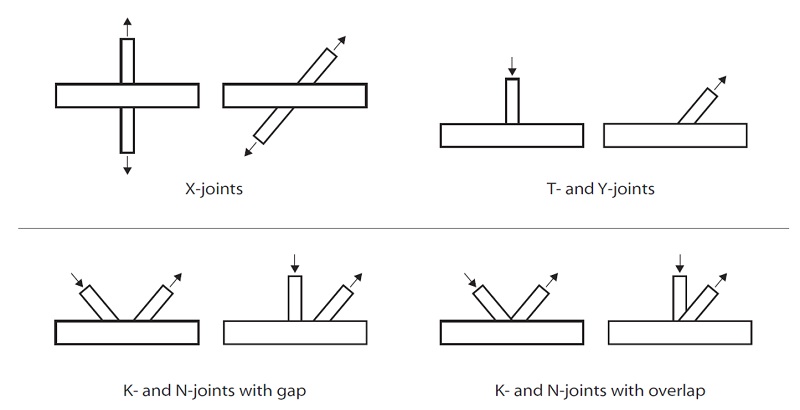
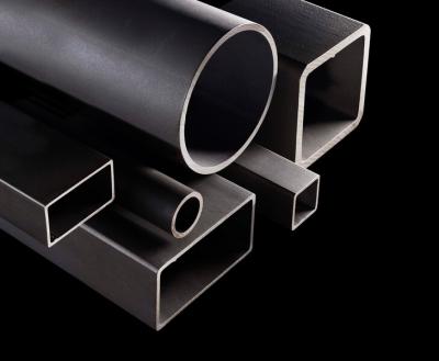
Structural hollow sections are available in a wide range of square, rectangular, circular and even elliptical shapes. From a fabrication point of view, the shape will have an effect on the cost and it is important to understand what impact the initial design decision could have on the project at a later date.
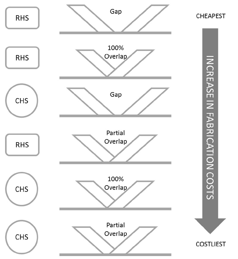
Just looking at K-joints as an example, the shape of hollow section and choice of either gap or overlap will make a difference to the fabrication cost. The cheapest solution is the RHS gap joint with the most expensive to fabricate being where a partial overlap joint is used with CHS sections, as seen in the diagram below.
Traditionally, the design of lattice structures is based on pin-jointed frames, with their members in tension or compression and the forces noding (meeting at a common point) at the centre of each joint. The usual practice is for the members noding on the centre line of the chord to produce a joint with no eccentricity. In reality this is rarely possible when looking at joint design as, in order to satisfy the criteria for minimum gap or overlap, some eccentricity is generally introduced.
Eccentricity is not necessarily an inconvenience for the designer, as long as this is within certain parameter limits. This ensures that the geometry of the joint in question is consistent with the empirical data used to derive the design equations. If the parameters are satisfied then the stiffness of the chord will be such that it can be assumed that any secondary moments from eccentricity are resisted by the chord and not distributed to the brace members.

Joint design is always a compromise between various conflicting requirements, but in all cases, joints must be designed to not compromise the integrity of the structure and so a thorough process of checking the integrity of all joints is always required. There are a few simple rules which can be followed to help in efficient joint design:
Checking each joint for the relevant failure modes and integrity under the design loads is often seen as complex and time-consuming, but at Tata Steel, we have produced a useful tool which can help in performing the relevant calculations. The software is more than just a calculation as it also highlights any failure modes plus indicates what is required to improve the capacity.
We always ensure that our joint design software is as up-to-date as possible, taking account of the latest learnings on joint design. This software is available free-of-charge from our technical design team.
To fully understand the details of joint design and the types of calculations required, we have also
Our range of both hot finished and cold formed structural hollow sections is one of the broadest available including the leading range of true hot fin..